The Balda Baldina Camera – Servicing Notes

I bought a Balda camera along with a Kalimar Reflex medium format camera from a flea market seller. I hadn’t heard of the Balda before, but I offered to buy both for a lower price on the Kalimar. The Balda needed a full service because it had corroded parts, a non-working shutter and peeling leatherette. Despite this, I was satisfied with the price I paid for both cameras.

Back home, I focused on the Kalimar and put the Balda aside. A few weeks later, I took out the Balda camera to examine it and learn how to service it.

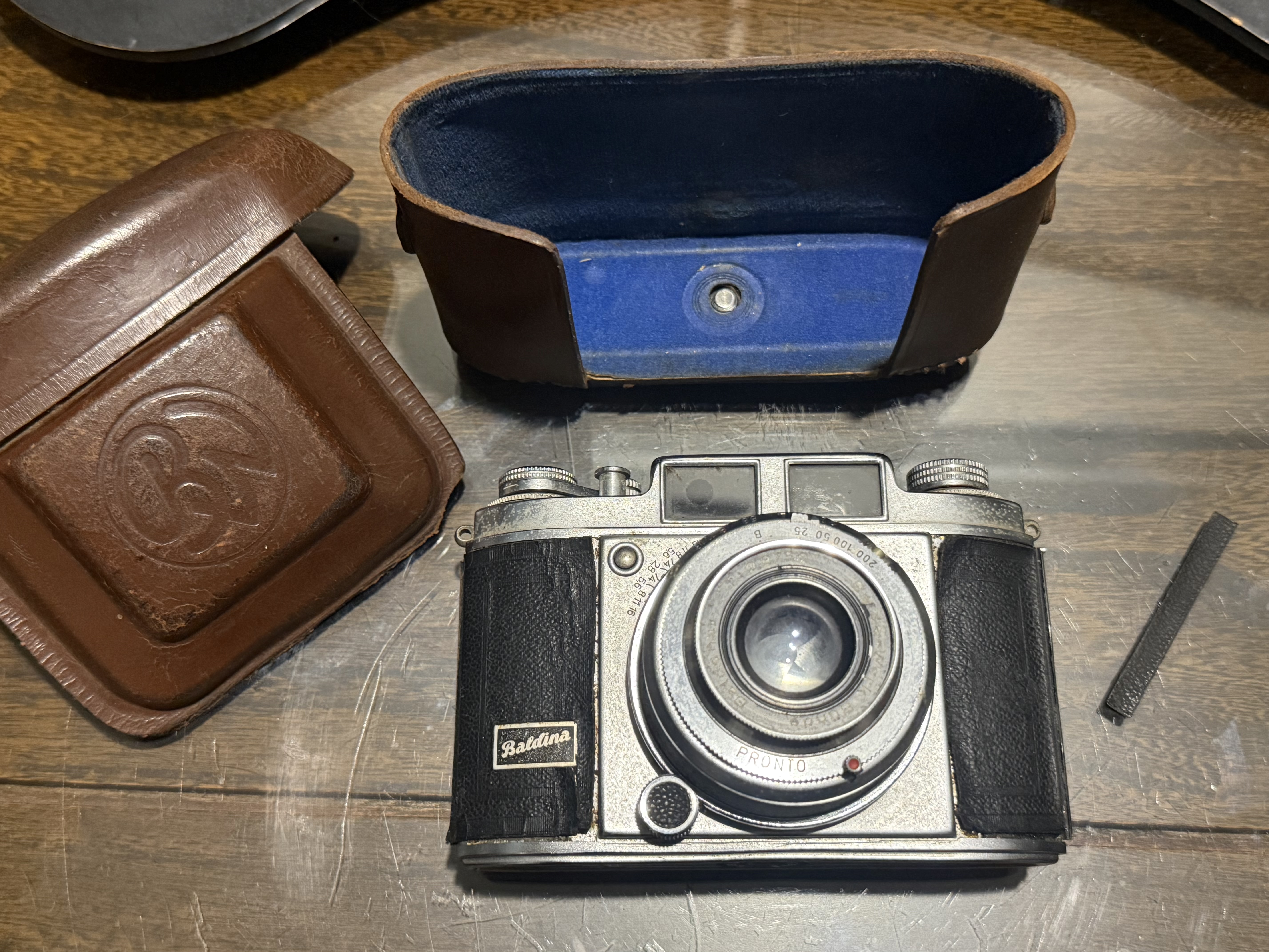
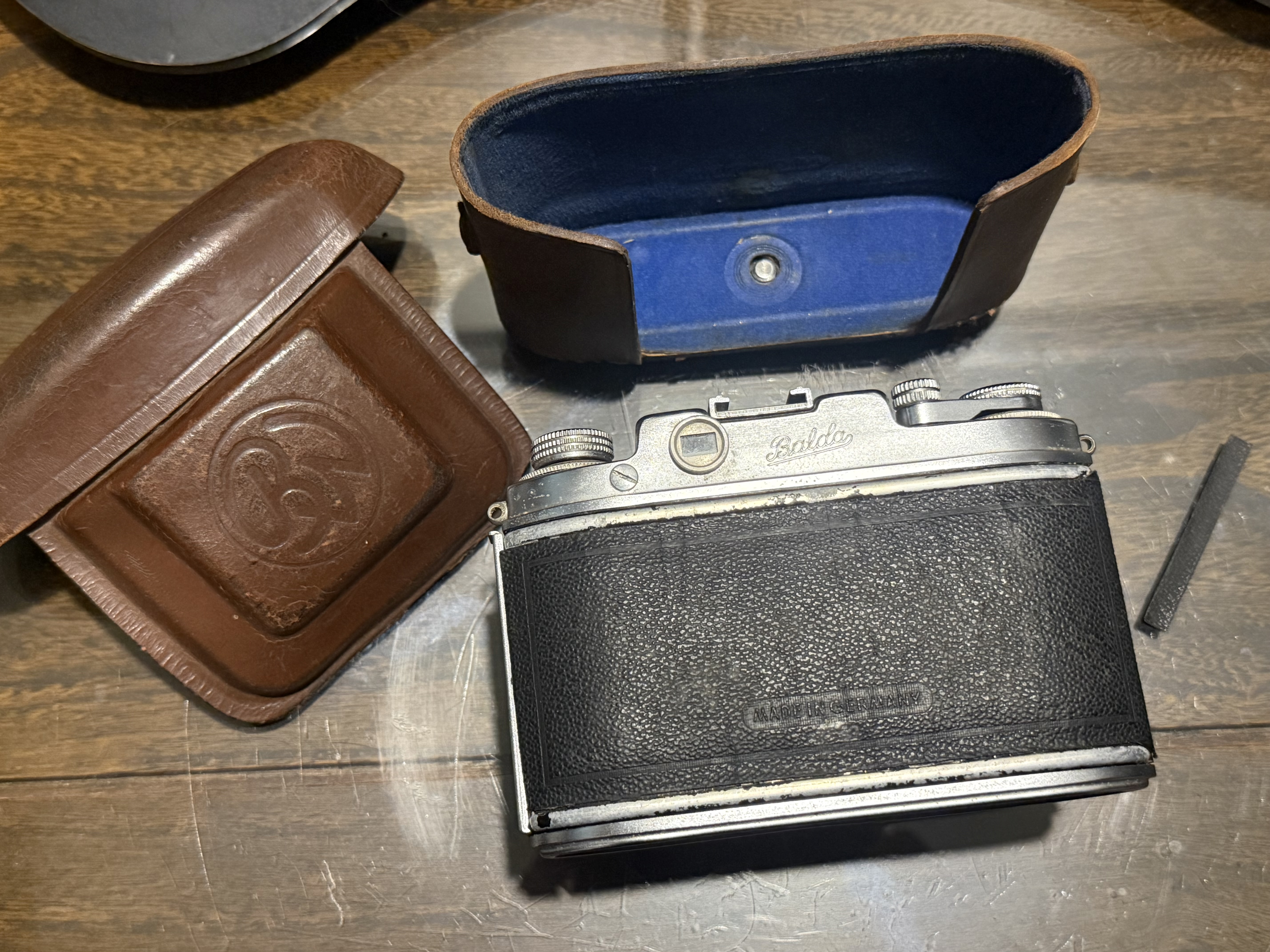
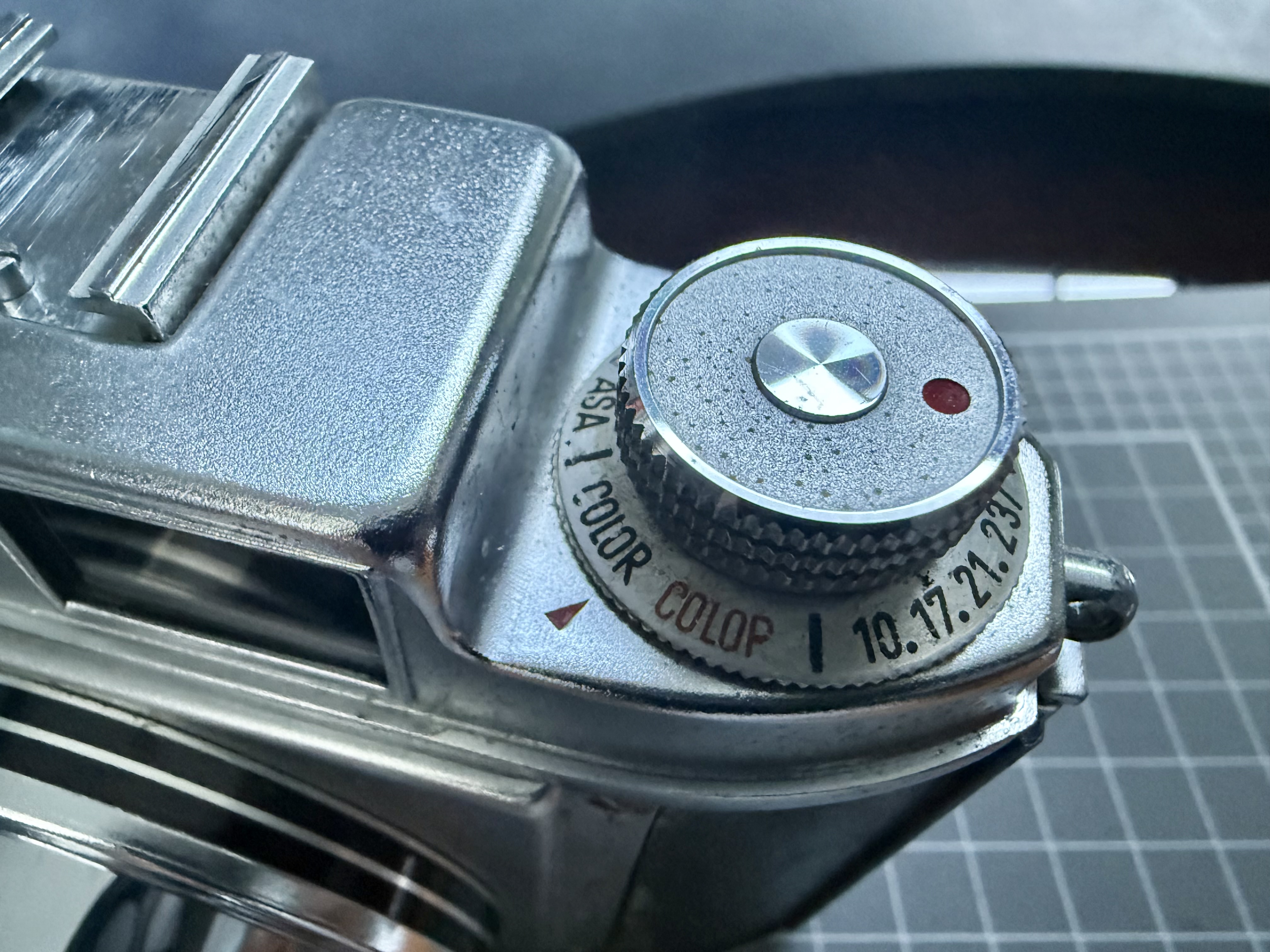
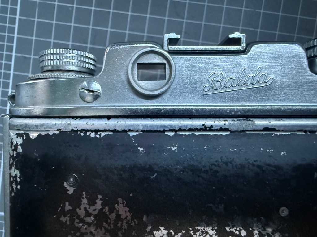
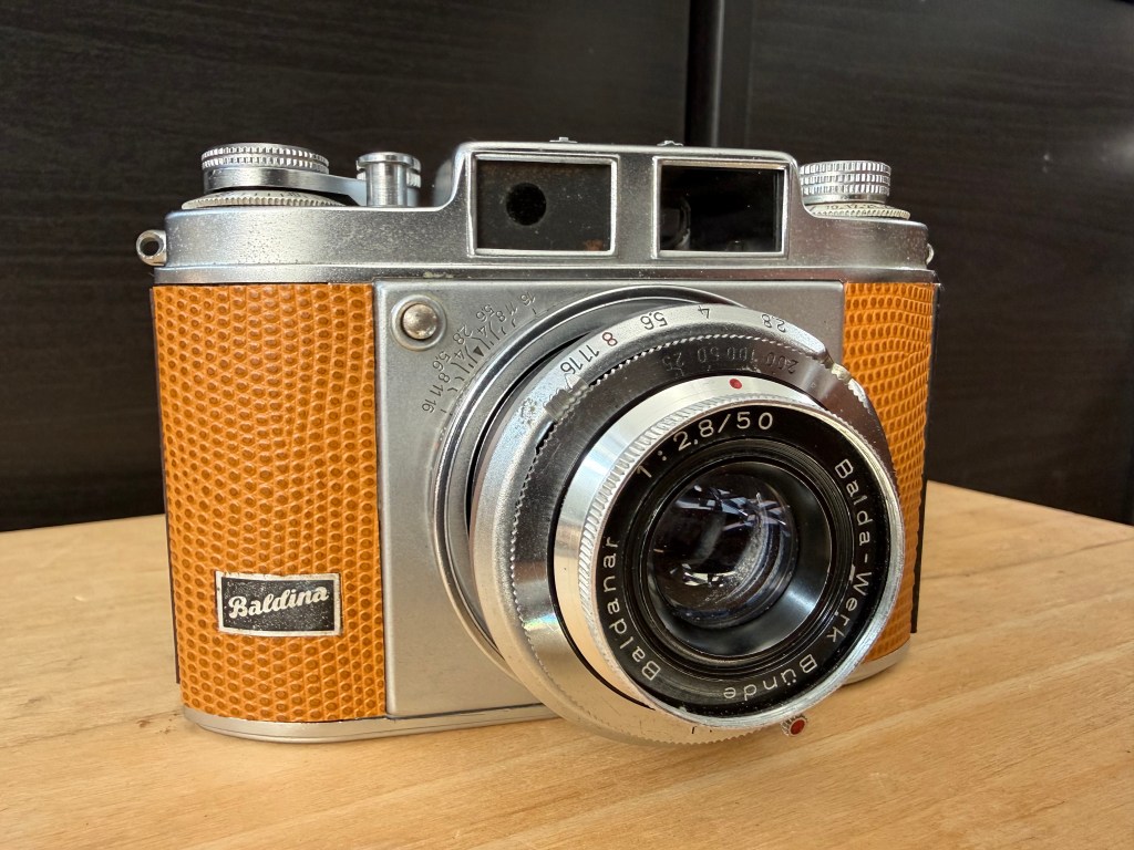
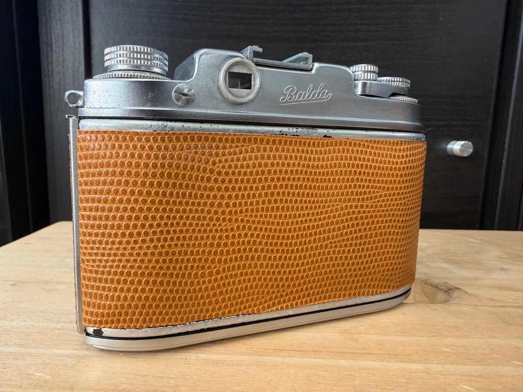
The Balda Baldina was a viewfinder camera from the mid-1950s made by the German company Balda-Werk. Although it resembled a rangefinder camera, it was not one. To reduce costs, Balda-Werk produced both rangefinder and viewfinder versions using the same body. The rangefinder version was called Super Baldina, while the simpler viewfinder version was just Baldina. Balda-Werk offered these cameras with various lenses and shutters. My version had an in-house Baldanar 50mm f2.8 lens and a non-working Pronto shutter.

I am writing this blog because I couldn’t find posts about servicing or disassembling the Balda Baldina or Balda Super Baldina cameras. Here are my notes on how to service and reassemble the parts of this camera.

I began by carefully taking off the leatherette from the camera. I hoped to reuse it when putting everything back together, but it was too damaged and cracked.

I next removed the top cover.

The Baldina does not have a rangefinder, merely a viewfinder prism

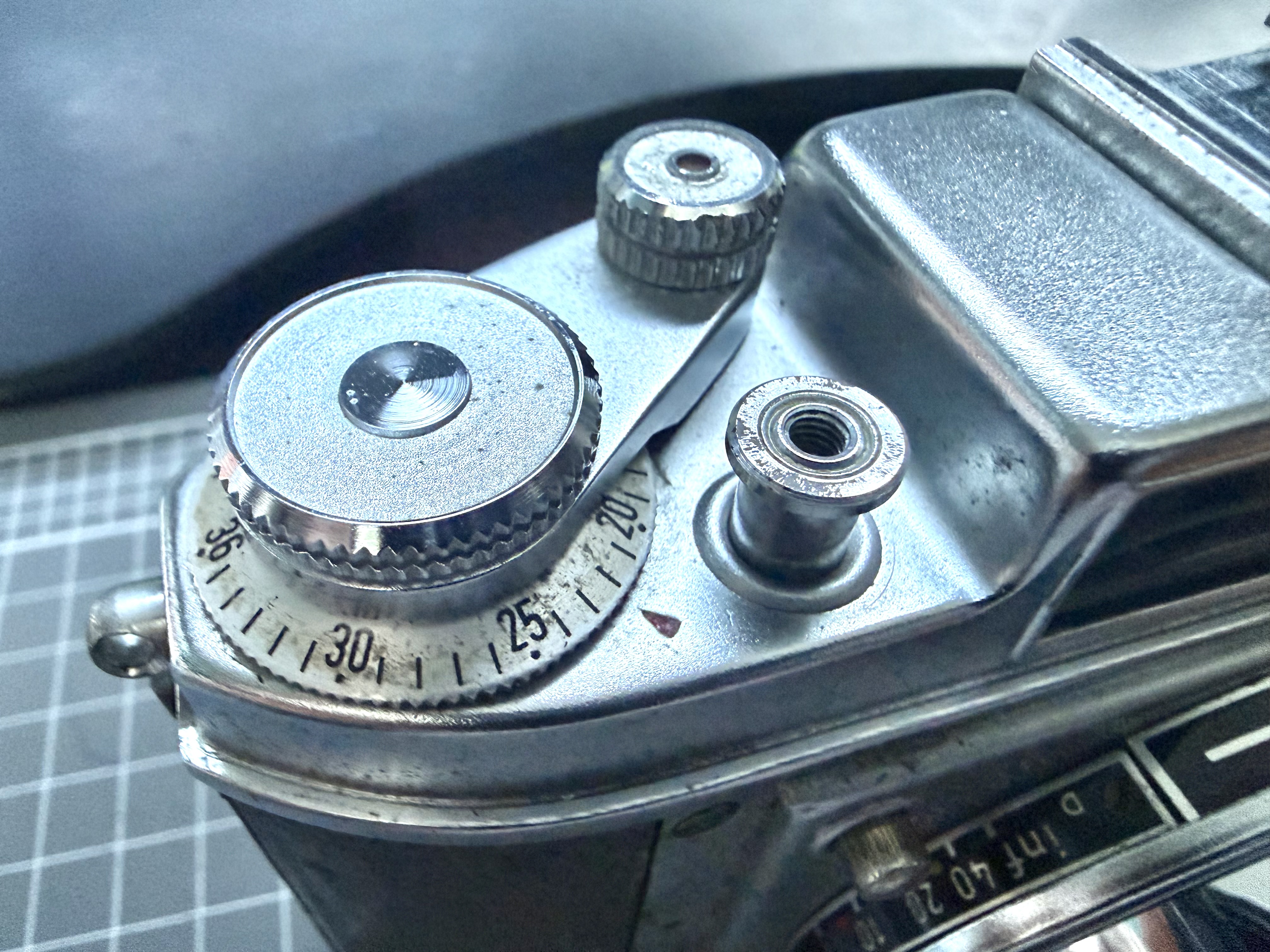
To remove the film advance lever untwist the cap counter-clockwise. The film rewind knob is removed by opening the film door, jamming the film prongs with the blunt end of tweezers, and turning the knob counter-clockwise. After unscrewing the neck-strap lugs on both ends, carefully take off the top cover, avoiding damage to the viewing glass.

The screw on the left does not screw to anything, I suspect it is for easy access to adjust the rangefinder in a Super Baldina

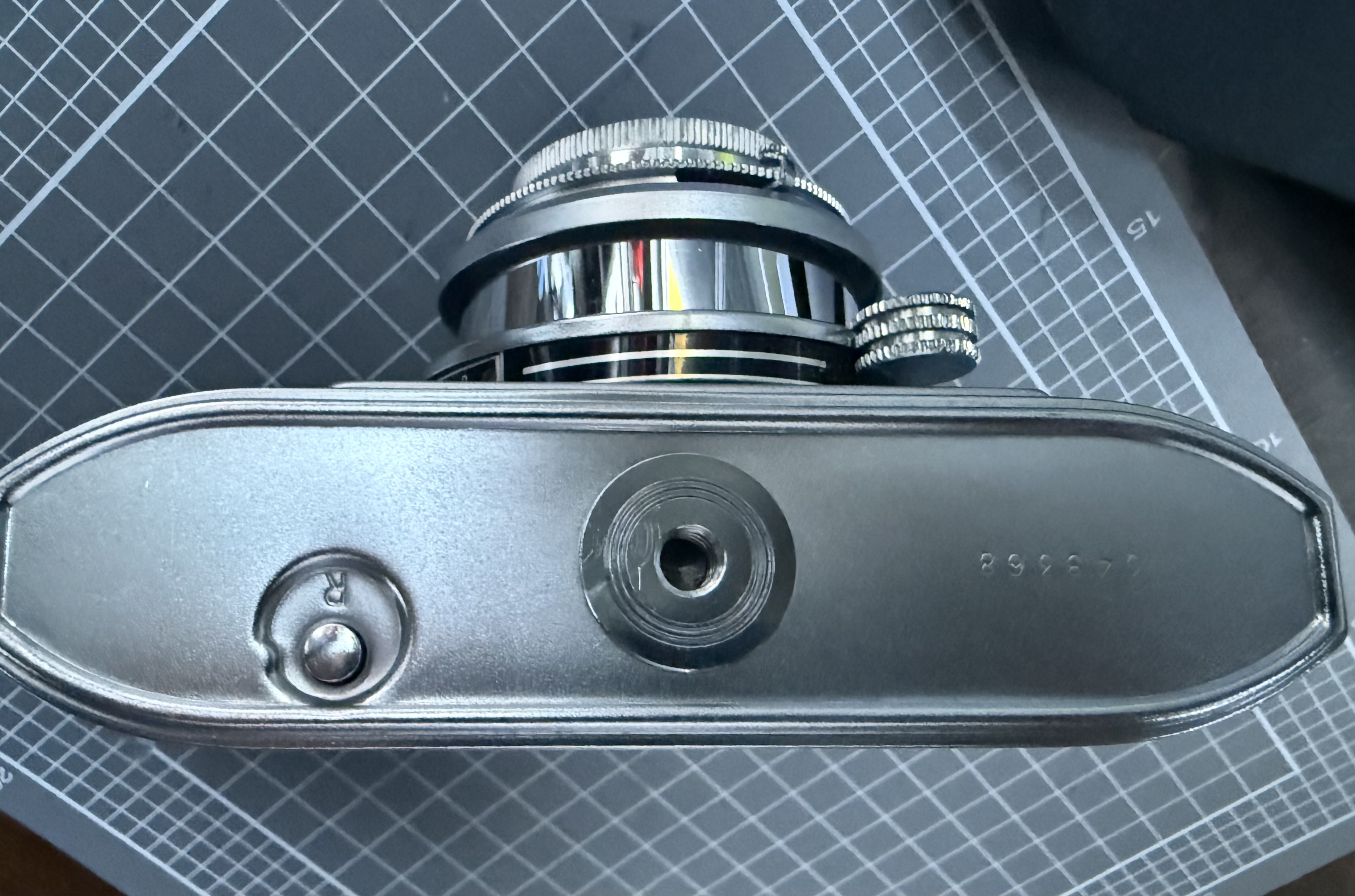
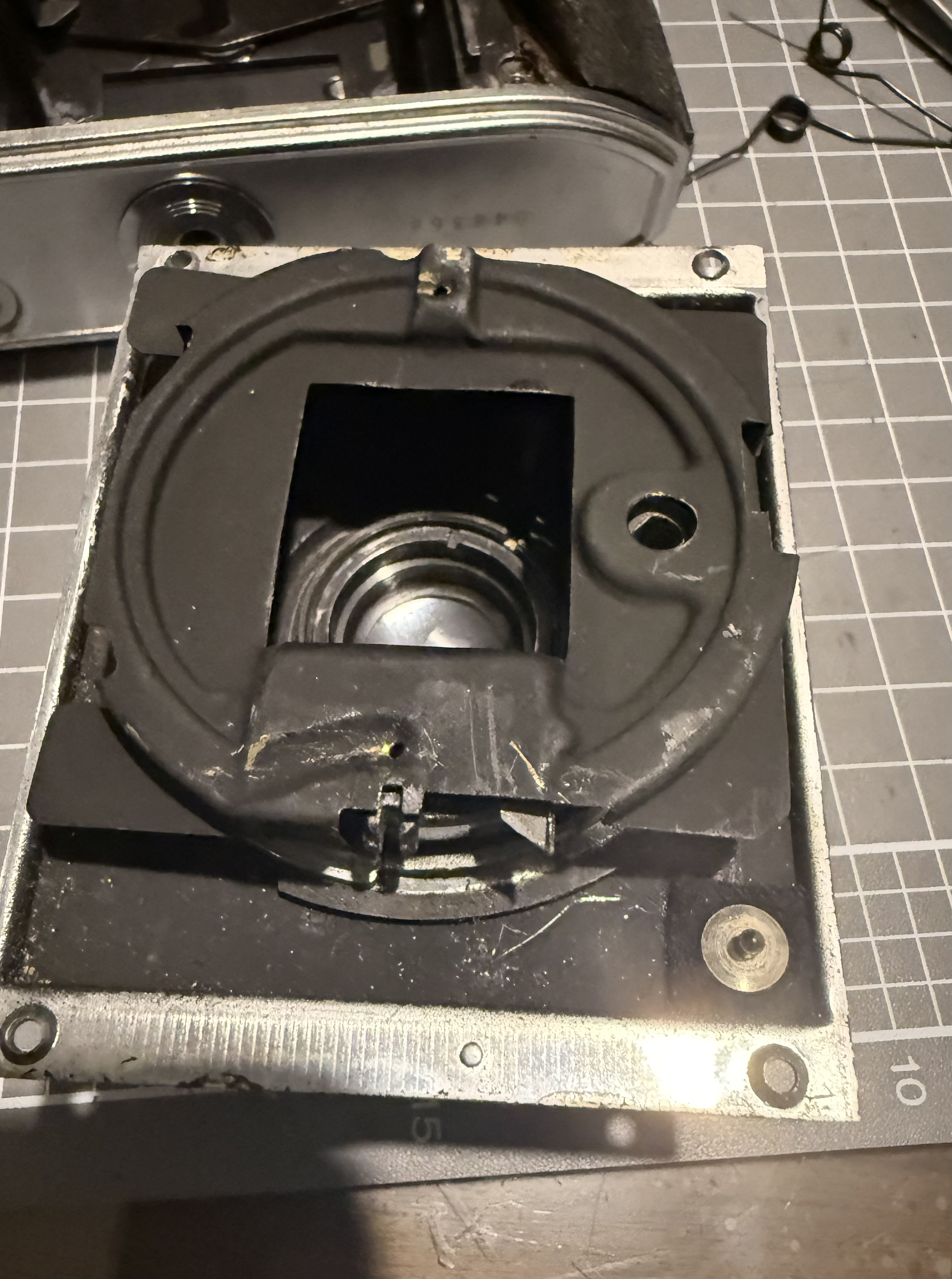
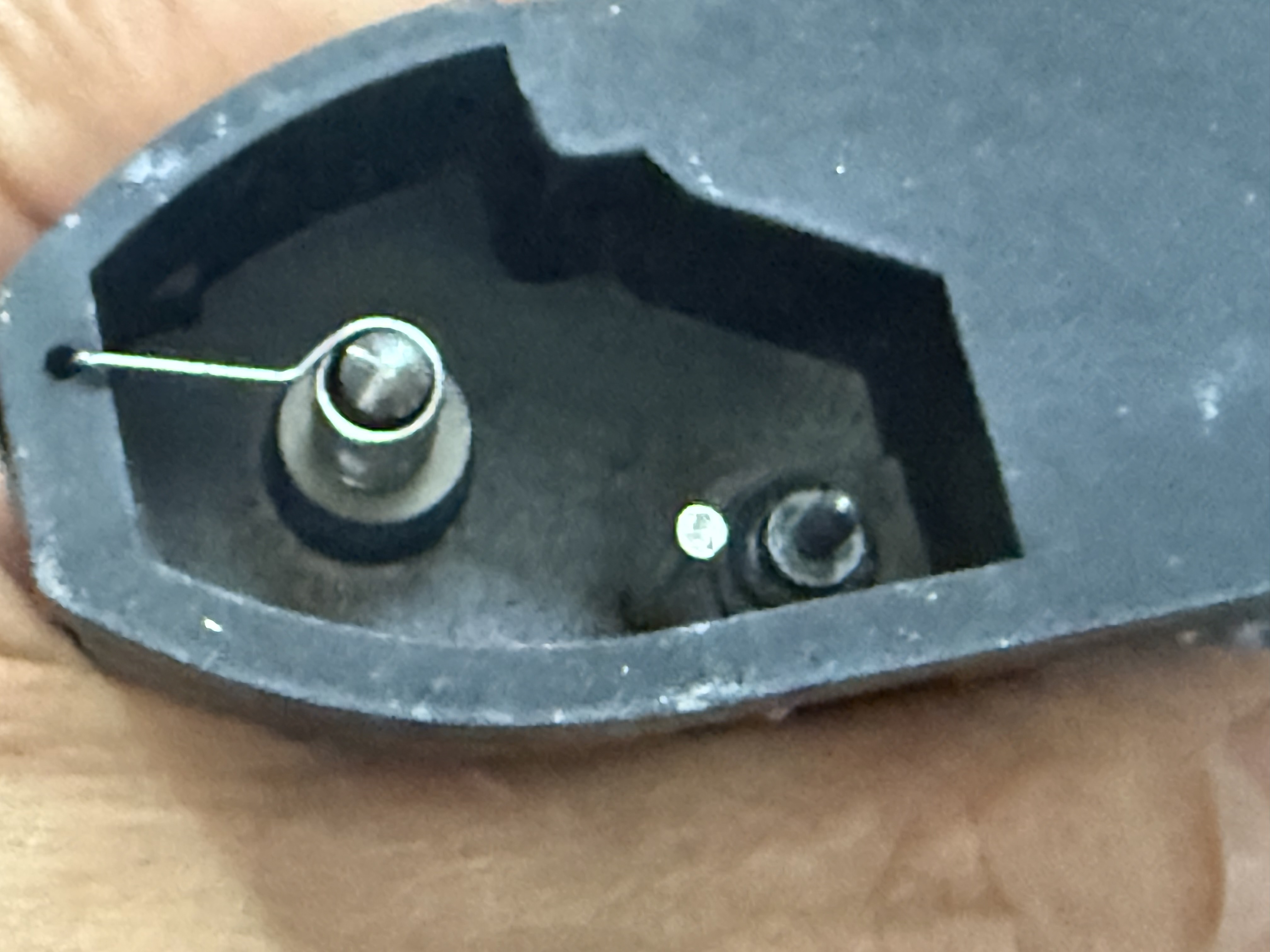
I initially didn’t know how to take off the bottom plate since there were no screws visible. I removed the front lens and shutter housing and found a big screw inside that secured the tripod mount and bottom plate from the inside. When reassembling, I realized there’s a way to access it without removing the front lens and shutter housing, as it’s nearly impossible to put the housing back on if the bottom plate is reattached.

Both the Baldina and Super Baldina share the same camera bodies and have collapsible lenses that pop out when you press the button on the top left of the lens housing. The lens does not use helicoids for focusing; instead, the focusing knob moves the tube in and out. When reassembling the lens housing, it is easiest to set the focusing knob at the midpoint between the nearest and infinity focus.

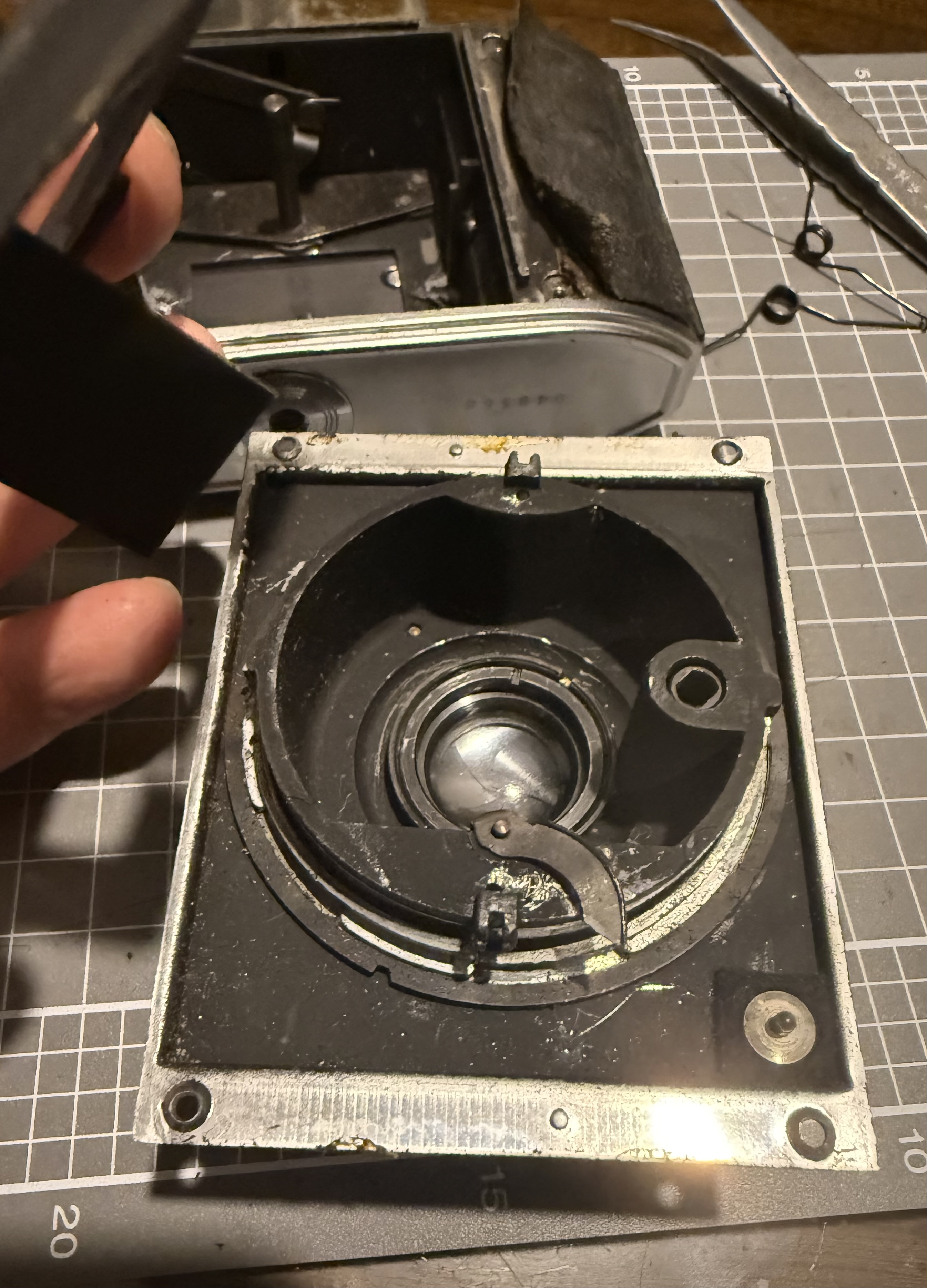
There are four screws that hold the front lens plate to the body. The two screws on the left have larger heads, while the two on the right have smaller heads. Be sure to put them back in the correct spots during reassembly to ensure a flushed fit.

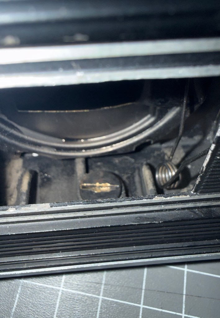
When taking off the screws, hold the front lens plate firmly onto the body. The collapsible part of the lens tube is under tension from two large springs that aren’t tightly secured inside. You should extend the lens tube before unscrewing the plate to lessen the tension on the springs. In my case, the springs popped out when I removed the front lens plate.

Later, I discovered that the springs are held in place by two holes in the body and two on the lens tube. To reassemble, first secure the springs in the holes, then push the inner plate to hold the springs under tension. Next, attach the front lens plate while making sure the collapsible tube release button and shutter cocking lever fit into their holes. This was the hardest part of reassembly. The design is poor, and it took several attempts to get everything back in place. It’s not impossible, but it becomes very difficult if the bottom camera plate is already attached.

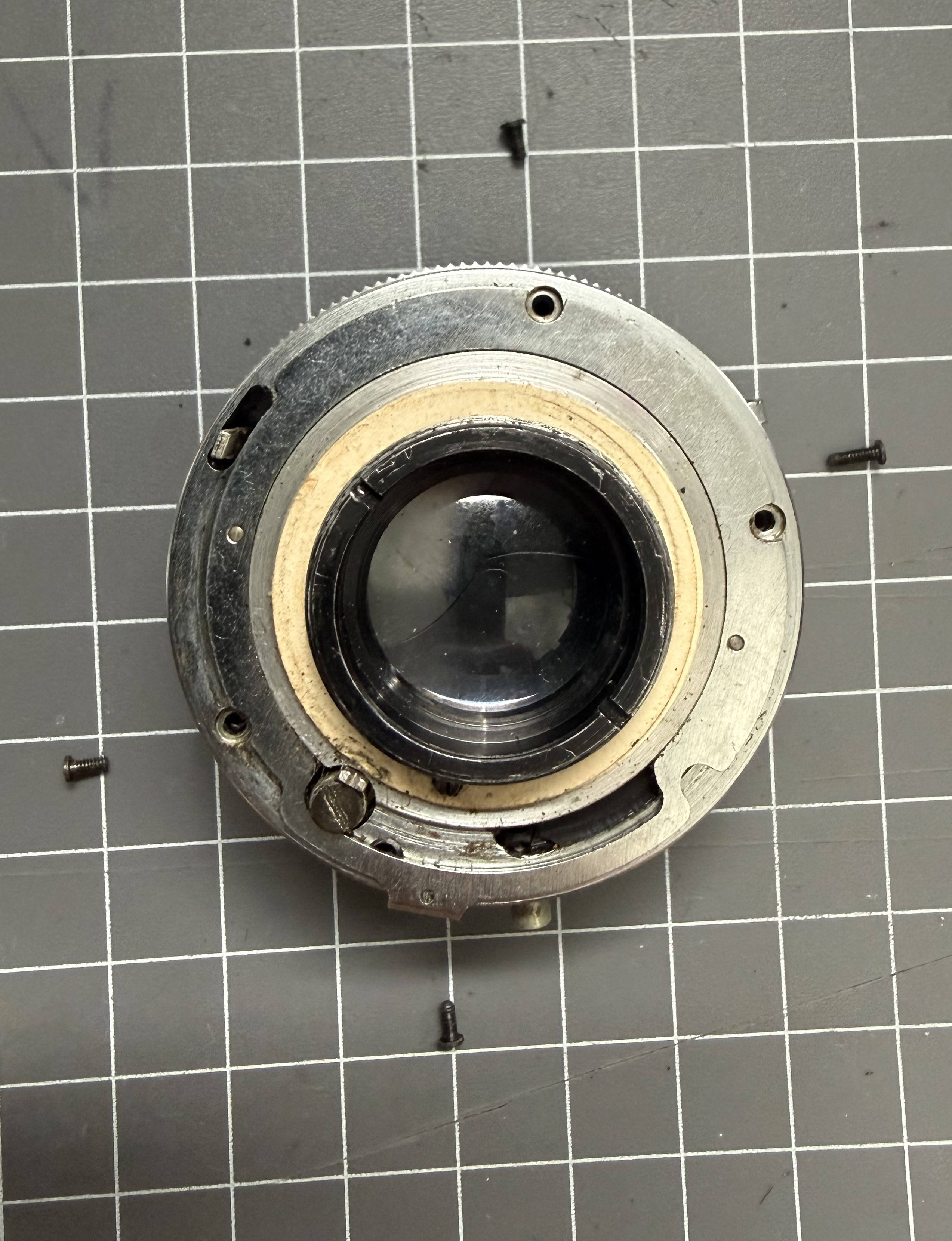
Compared to the front lens plate, the lens and shutter are easier to handle. They are attached to the front plate with a retaining ring at the rear, which can be removed using a lens spanner.

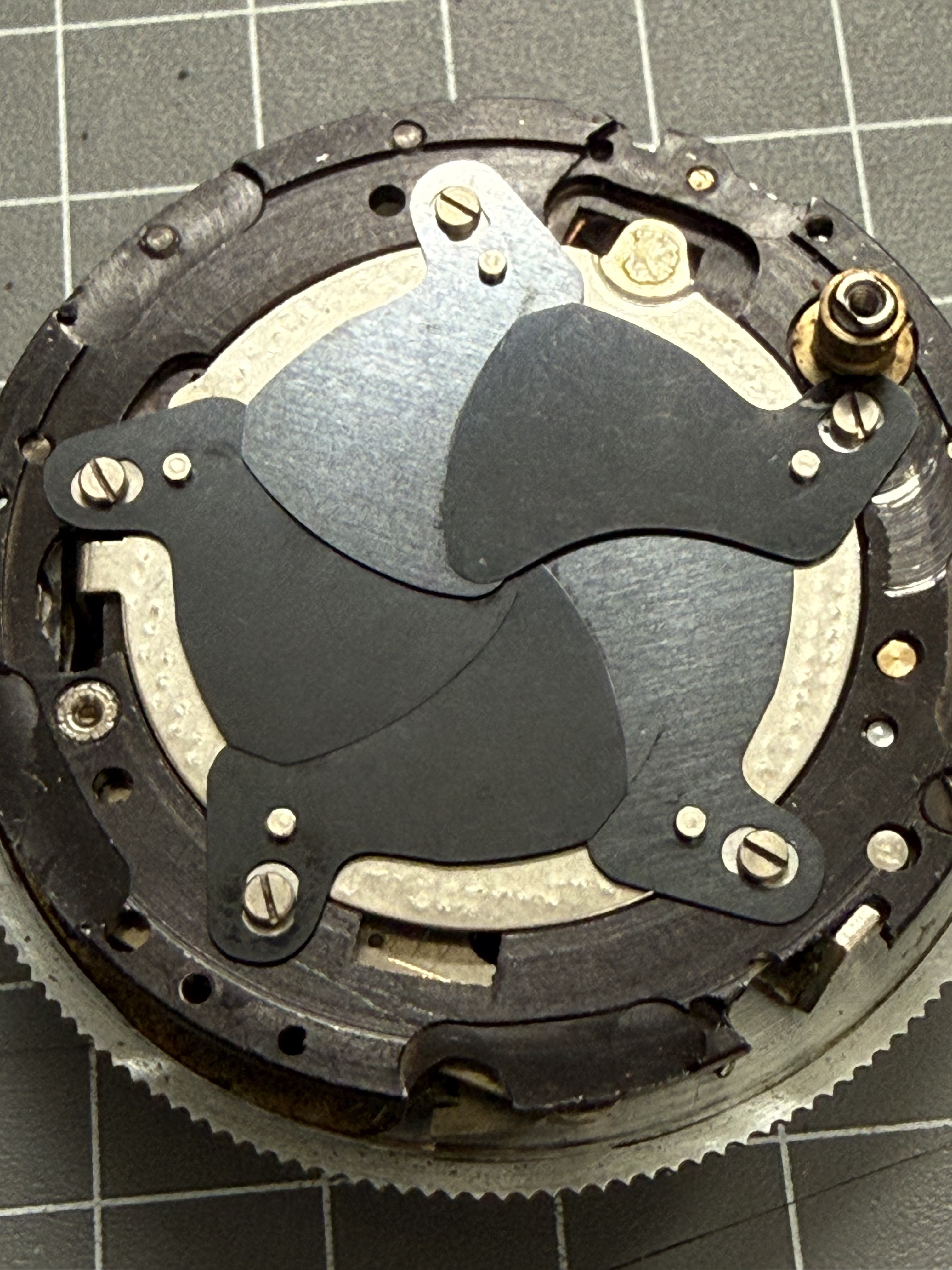
I accessed the shutter blades from the rear since I couldn’t unscrew the front lens elements despite using acetone and naphtha. When taking apart the Pronto shutter from the rear, be cautious of the cardboard shims and four screws, one of which is longer and also serves as a stop for the spring that tightly closes the shutter blades. Remember where each part goes. The shutter blades can be easily removed, cleaned, and reassembled, so note their positions before disassembly.

Later, I managed to remove the front lens element to access the Pronto shutter from the front. I won’t explain how to service the shutter, as you can find that in videos online.

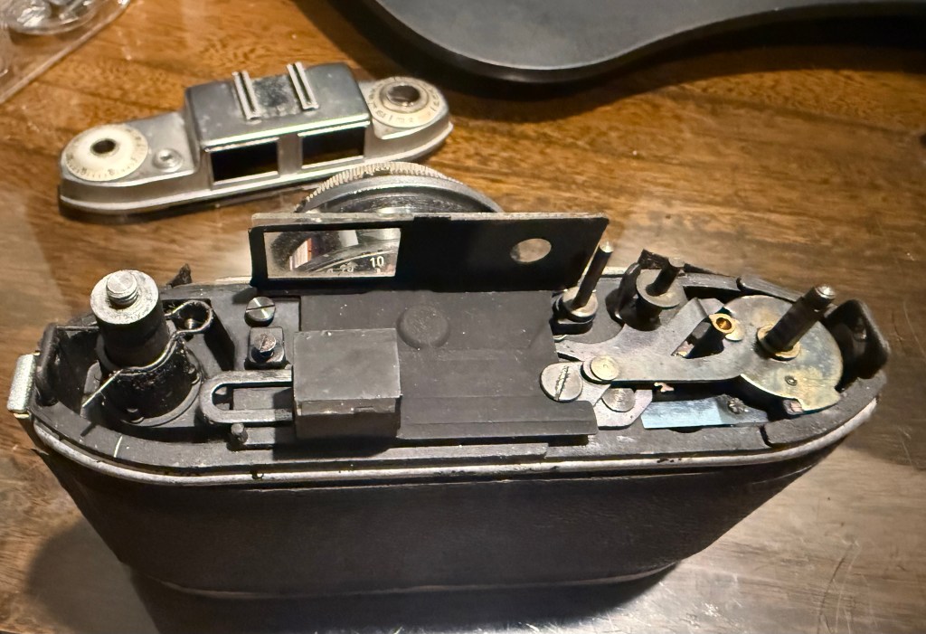
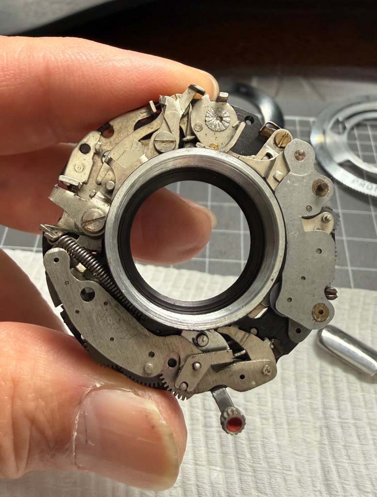
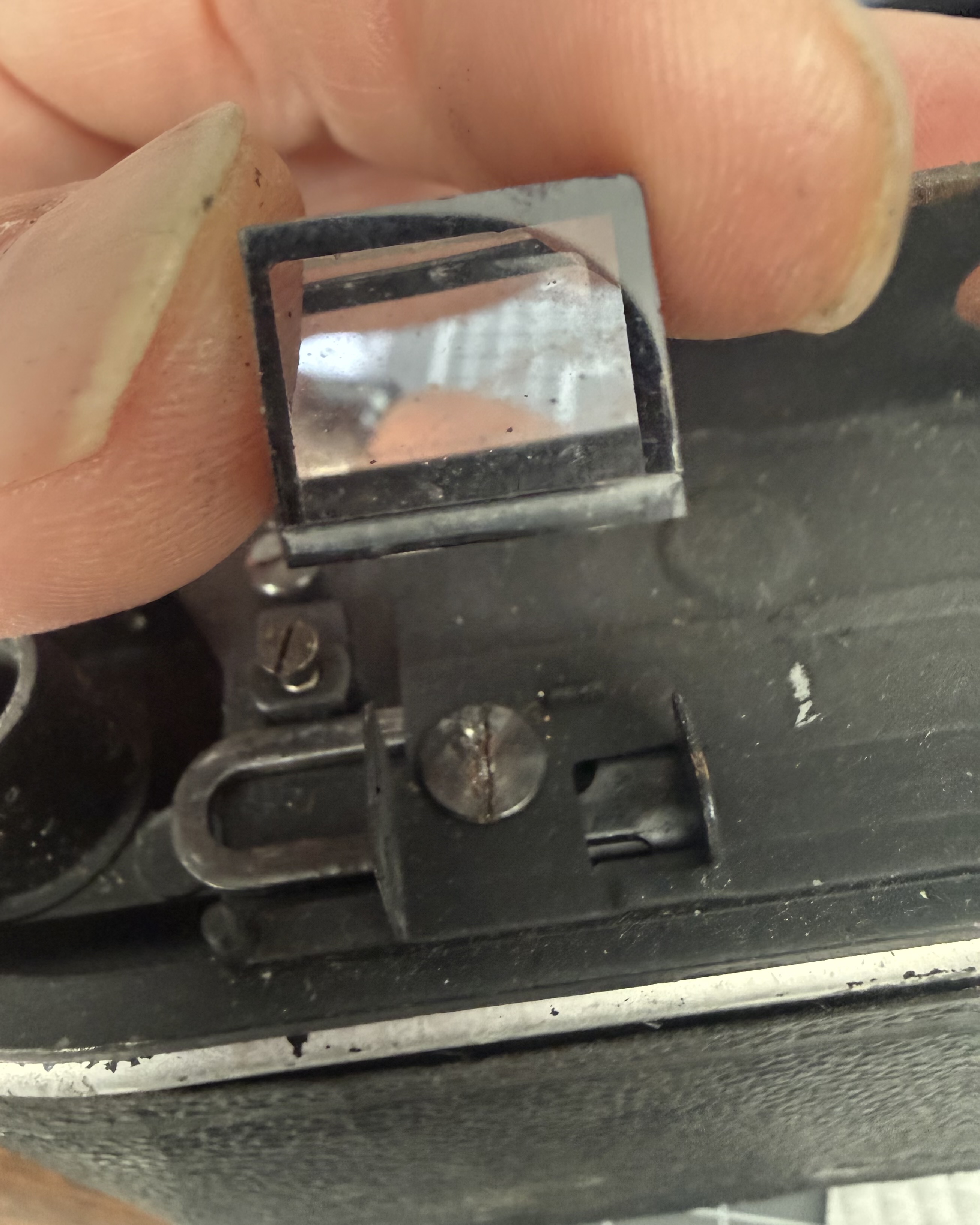
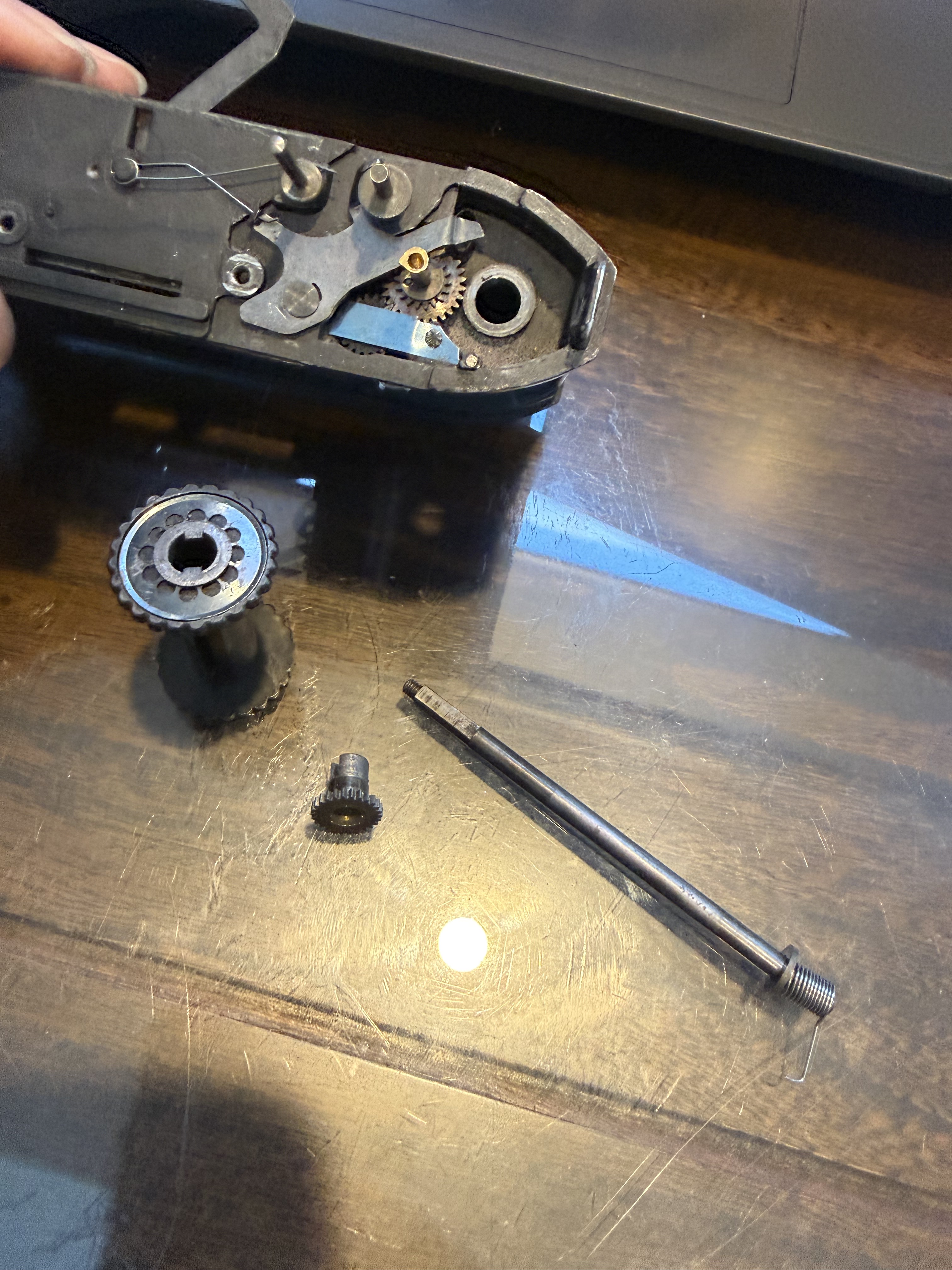
To service and lubricate the film advance mechanism, first remove the viewing prism and the viewing glass housing. Gently wiggle the prism out of its holder, and unscrew the exposed screws to take off the viewing glass housing.

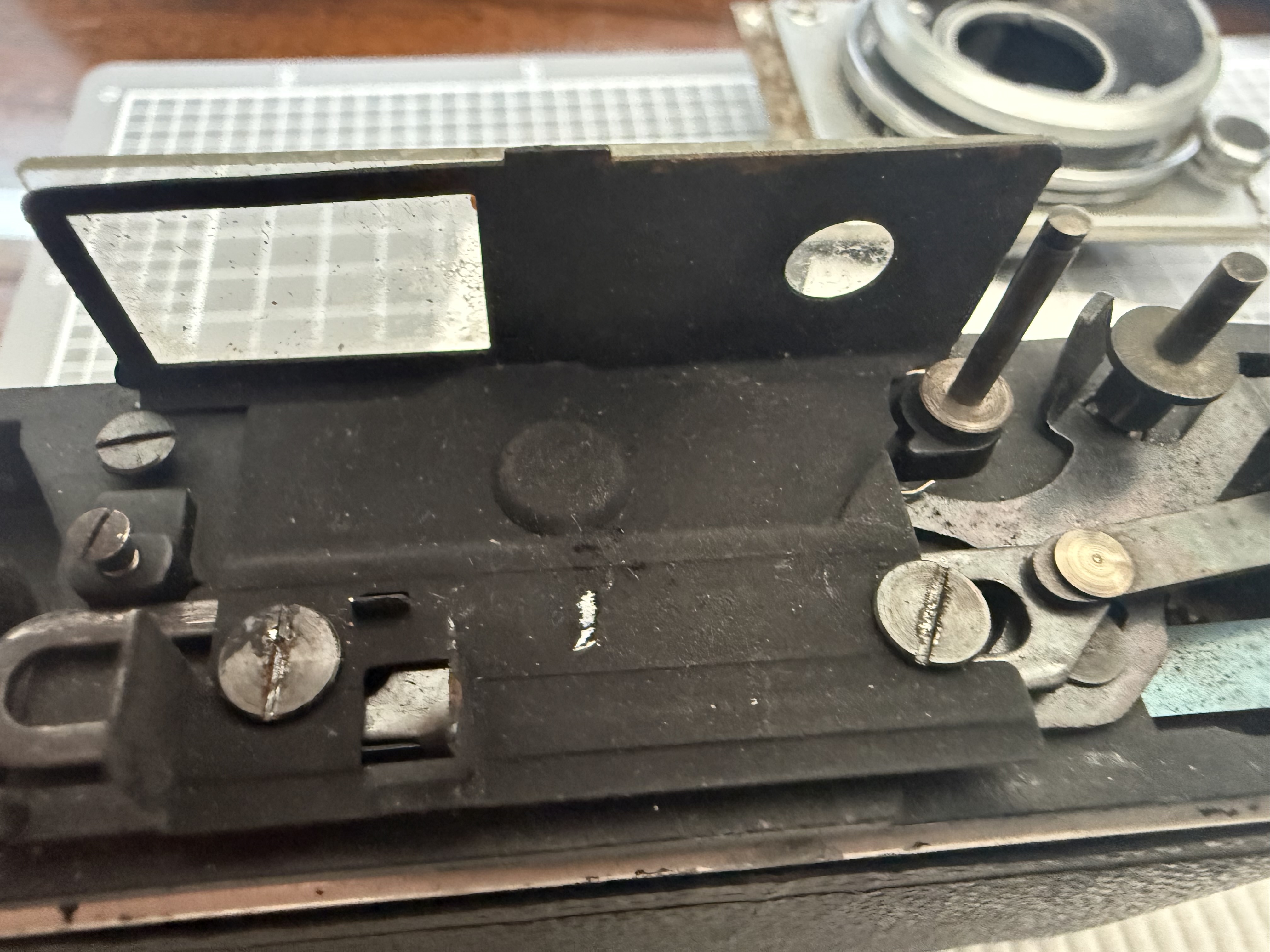
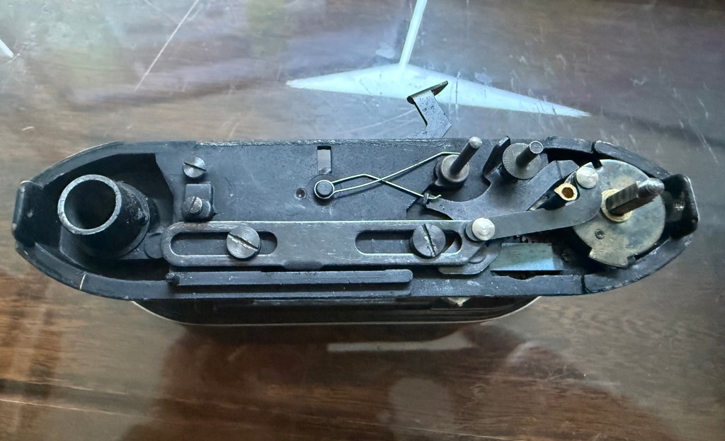
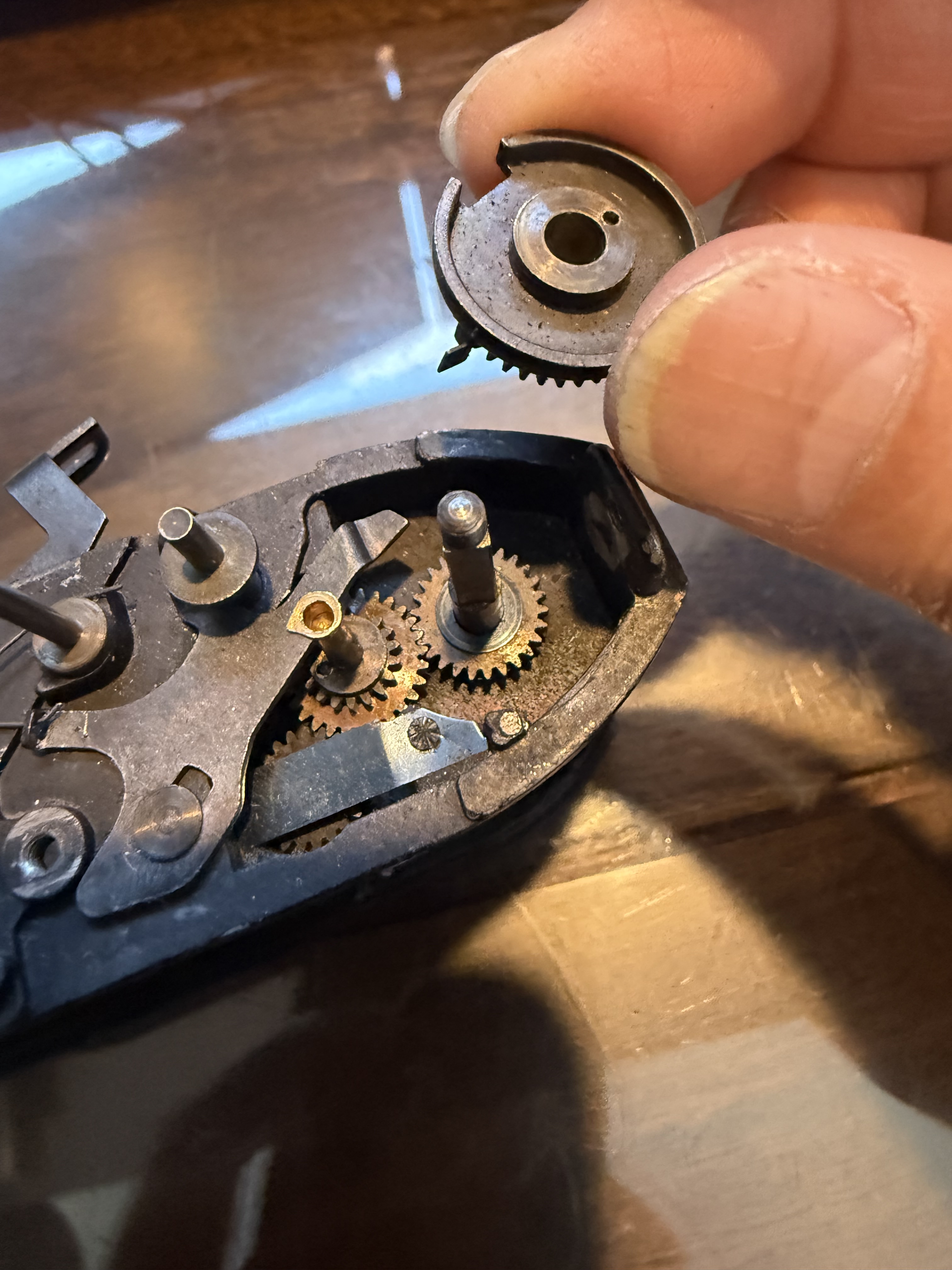
Note how the film advance and shutter cocking mechanisms are put together as you take them apart. It’s not a complicated mechanism, but understanding how they work before disassembly is important.

Once everything is cleaned and lubricated, reassembly is the reverse of assembly. Start by putting the lens and shutter mechanism back together, followed by the film advance mechanism, and then attach the lens front plate to the body. This part is tricky because of the springs, so be patient, take breaks, and it will fit together.

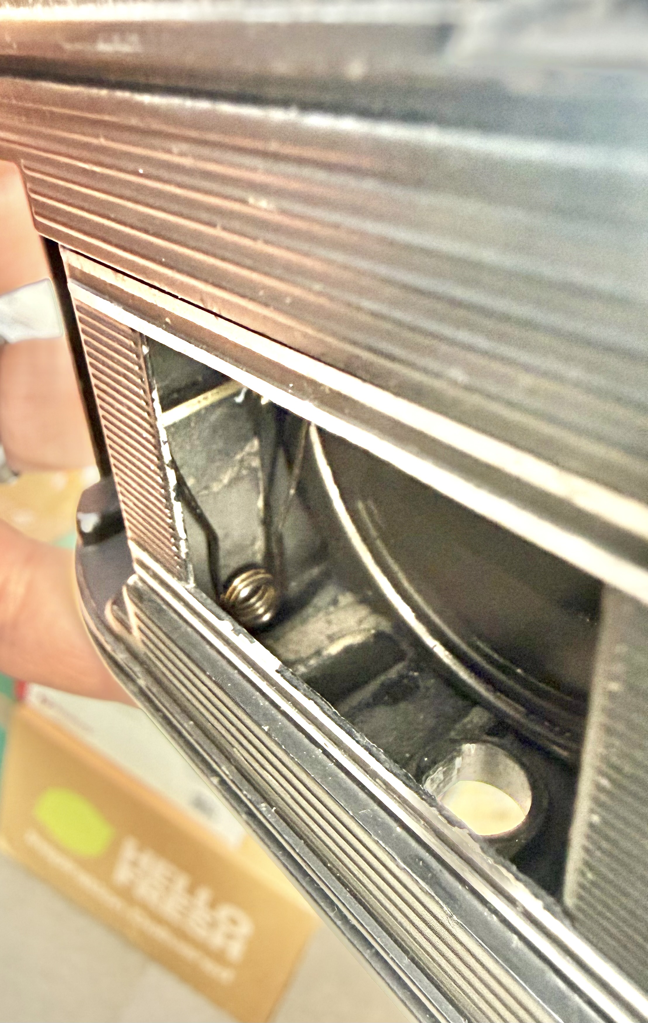
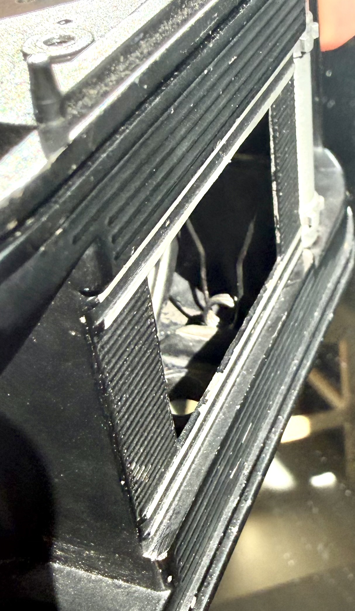
The lens tube springs are fixed in the camera to two small holes at the front and back.

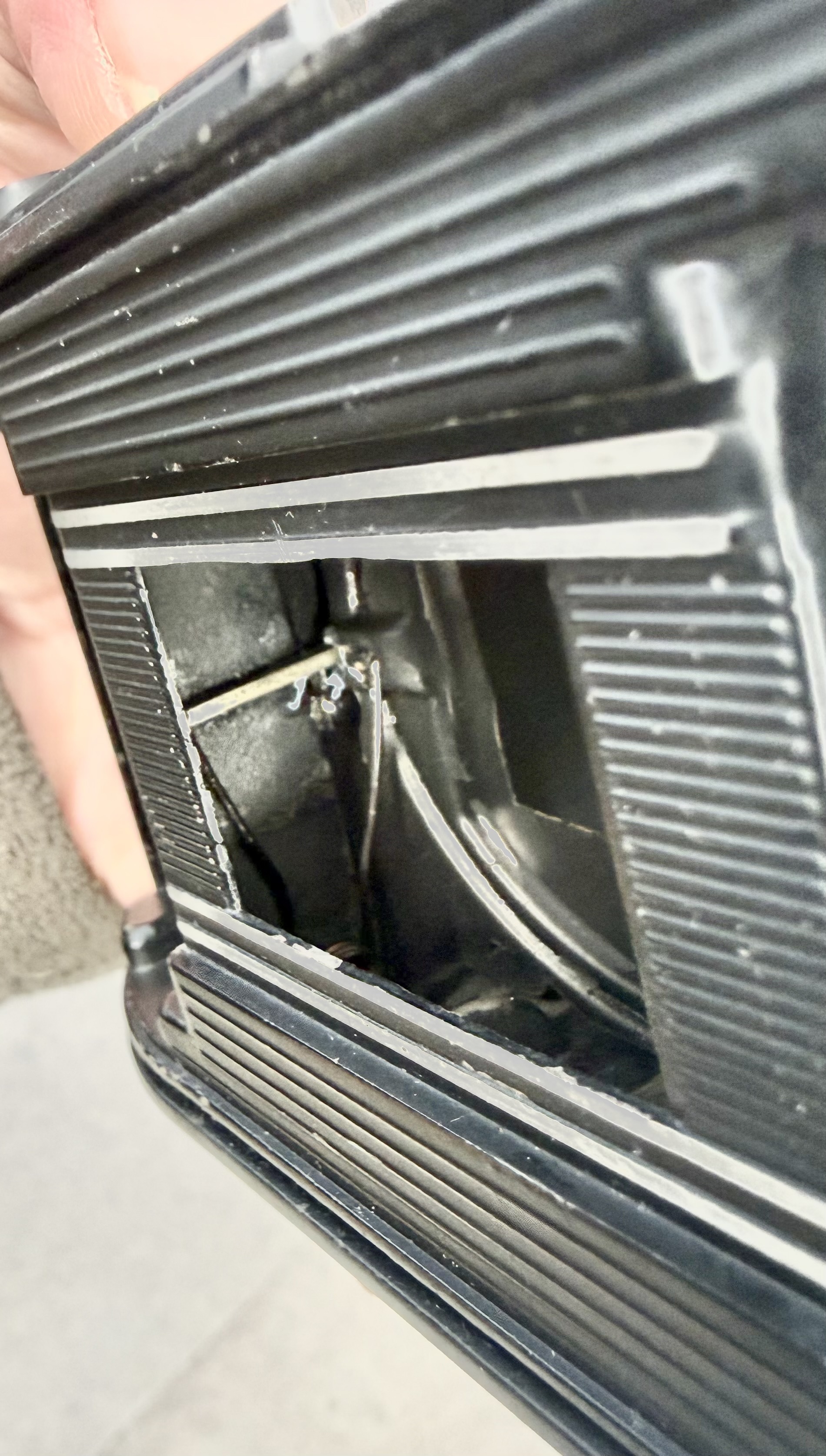
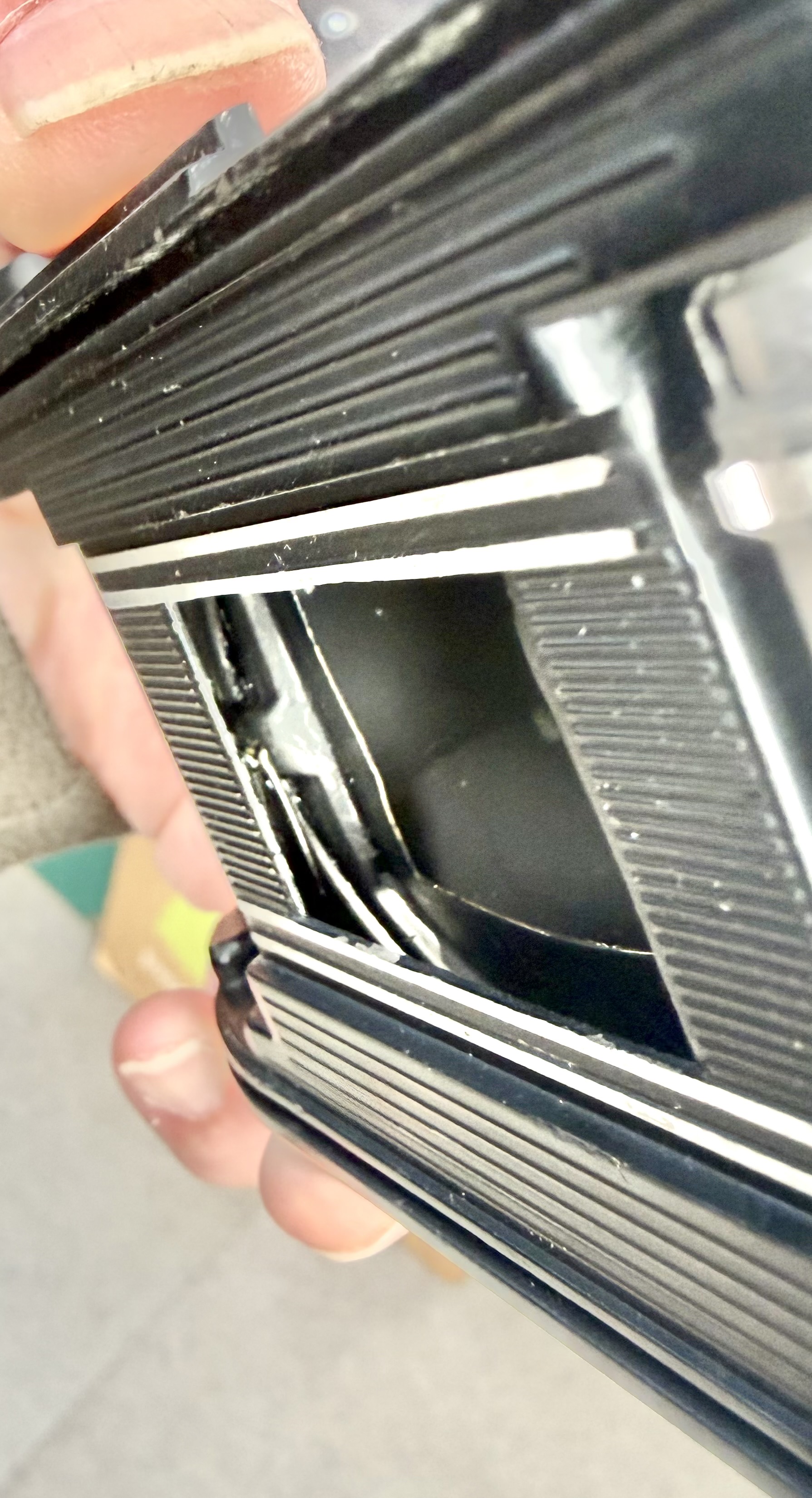
In the first picture above, the lens tube is extended. In the second picture, the lens tube is retracted. Note that the springs are under maximum tension when the lens tube is retracted. Hence when you press the lens release button, it pops out very quickly.

Once the front lens plate is re-assembled, then re-assemble the bottom plate first. Place the tripod mount into the hole in the bottom plate and then screw on the circular screw from the inside of the film chamber (with lens tube extended) to the tripod mount to secure the bottom plate.

Finally check that everything is connected properly i.e. film advance working properly, shutter cocks, shutter releases properly, before re-installing the viewing glass and prism and the film rewind shaft. Once everything is in place, re-assemble the top plate, film advance lever and film rewind knob and camera lugs.

Below, Balda Baldina fully serviced with new skin.

Thanks for reading.

Why I Like Lenses from the 70’s and 80’s

Recently I acquired a Nikon SLR with an AF-S DX Nikkor 35mm f1.8 G lens attached to it. While I was not planning to get the lens, I thought this was a bonus.

This particular Nikon lens was released in Feb 2009 primarily for Nikon’s DX range of DSLRs (digital SLRs). The lens was primarily targeted as an inexpensive, large aperture option for users of the entry-level (D40 / D40X /D60) series of DSLRs. It is small, light and cheap and had relatively good reviews. It had the silent-wave auto-focusing system, meaning that the autofocus mechanism was in the lens and not the body, theoretically making it faster to autofocus.

When my lens arrived, it looked in good condition. The glass was clear, the focusing ring was smooth. However, when I attached it to the camera, it could not focus fast enough. It kept hunting for focus. I thought it was the camera body, so I changed the body. Same issue. Cleaned the electronic contracts, tried it outdoors in bright light and larger apertures, no difference. The lens still hunted for focus.

Eventually I looked to the internet to see if anyone else had similar problems. There were a couple of posts mentioning focus hunting issues with this model of 35mm lens. One poster, disassembled his lens and cleaned the gears of the silent-wave mechanism. Apparently that got rid of the problem. I decided to do the same.

Starting with the rear of the lens, I unscrewed the 4 small screws securing the mounting ring.

Next 3 screws to come off were the ones holding the black plastic part of the lens mount in place.

Before the metal lens mount ring could be detached, the lens contact points had to be released from the mount. This was held in place by 2 small screws. The lens contact points are connected to the lens CPU by a cable, hence the contact points have to be detached before I could remove the lens mount ring completely.

Care should be taken when removing the lens mount ring from the barrel, as there are several rings of different thickness below the main ring that can fall off if you remove the mount quickly. All these rings are held together by an outer rubber ring which also comes off when the mount is removed. This is the first of many inferior aspects of this G lens construction that I noticed. Nikon lenses of higher quality do not have all these rings and there is no rubber holding rings together. In the higher quality Nikon lenses, the lens mount is one solid block of metal.

Once the lens mount ring and all the other rings are removed, the next step is to unscrew the single screw holding the focus selector switch in place. After this screw is removed, the lens barrel cover can be slowly slid out to reveal the inside of the lens. However, the focus selector is connected by wires to the CPU, hence, the lens barrel needs to be removed slowly leaving the focus selector dangling by the wires still connected to the main barrel.

Once the inside of the lens is revealed, you can see the silent-wave motor and focusing mechanism (top left picture), the contact points for correct autofocusing of the lens (top right picture), cables to the lens CPU (bottom left picture) and the lens CPU (bottom right picture). All these are held together on a plastic barrel frame. There is hardly any metal in the barrel. The use of brittle plastic for the barrel frame is another inferior construction feature to keep the cost of this lens low. Even the lens elements are held in plastic frames.

To access the silent-wave motor next, the focusing ring needs to be removed. In the pictures above, the lens is held by the focusing ring.

Turning the lens around, the first step is to remove the cover ring to expose the screws holding the focusing ring in place. Initially I was confused as to how to remove it as there is only one notch on the cover ring. Usually there are 2 notches directly opposite each other so that you can use lens ring wrenches to unscrew them. For this cheaper construction this cover ring is held by double-sided tape! All I had to do was to slowly pry it off with a small screw-driver.

There are 2 sets of 3 screws that can be seen once the cover ring is removed. Not sure which ones hold the focusing ring in place, I proceeded to unscrew the metallic screws. Wrong ones! Those hold the plastic frame that houses the front lens element. This is a first time I have seen lens elements housed in plastic frames! Another cost cutting construction by Nikon.

Removing the black screws finally released the focusing ring, which has plastic gear teeth that locks into the focusing gear (plastic as well) of the barrel.

With the motor mechanism exposed, I cleaned the motors and gears with 90% alcohol. After which I reassembled the lens mount but not the barrel cover to check if the lens focussing issues were resolved. Unfortunately, the lens performed no better.

Puzzled, I examined the barrel closer with my loupe. Sad to say, I noticed a crack in the plastic gear that moves the brass auto-focusing contacts. In fact the crack was more extensive, extending diagonally from the base of the focusing ring to the base of the lens mount. What!

The crack completely separates the ring that forms the plastic gear for the auto-focusing contacts. This was obviously the problem.

This lens must have suffered a knock previously and while the damage was not obvious externally, it caused a long diagonal crack in the internal all plastic frame of the lens barrel.

This will never happen in a lens constructed in the 70’s or 80’s, which have far superior metal construction. While the AF-S DX Nikkor 35mm f1.8 G lens looks nice, I wouldn’t recommend it for its cheap all plastic construction. An accidental knock on a wall, or a knock on a lamp post or a drop from the camera bag to a concrete floor will likely render the lens non-functional!

I am sticking to pro-level lenses or old metal lenses even if they don’t have fancy autofocus. The Nikkor of years gone by were quality “glass in metal”!

Nikon EN-4 Battery Lithium-Ion Conversion

I used to have two Nikon D1-series cameras – a Nikon D1 and a D1X. These, along with the D1H, were the first Nikon pro-level digital cameras – essentially Nikon F5 bodies with digital innards. These cameras were powered by the Nikon rechargeable nickel metal-hydride (NiMH) EN-4 battery.

Large and heavy, these batteries were also infamous for not keeping a charge after they have been used for a while. They were a bane for photographers using the D1 series cameras as they had to carry 3 to 4 of these heavy batteries on a photographic outing as these batteries were, on an average, good for about 300 shots each.

That was 20 years ago, the D1 series have long been superseded by newer models of Nikon pro-level digital cameras – D2 series and the latest of the pro-models, the D5. Nikon, cognizant of the shortcomings of the NiMH batteries, replaced the batteries of the new models with more reliable lithium-ion (Li-Ion) batteries.

I recently bought a 2.7 megapixel Nikon D1H camera on eBay for $50. $50 is a cheap way to shoot with a pro-level Nikon camera, albeit 2.7 megapixels. It came with 2 Nikon EN-4’s and 1 after market EN-4. One of the Nikon EN-4’s was dead – the charger couldn’t revive it anymore. I had seen another seller on eBay offering a Nikon D1X with a Li-Ion converted EN-4 battery. First time I had seen one of these and it looked like a good way to extend the shooting stamina of the D1H. I decided to play Dr.Frankenstein and revive the dead EN-4 that I had!

Scouring the internet, I came across a few posts describing how these batteries could be converted. The EN-4 could be configured in different ways but fundamentally the NiMH batteries in the plastic EN-4 casing had to be replaced with two 18650 Li-Ion batteries. 18650 batteries are so called because they are 18mm in diameter and 65mm in length. Each are rated at 3.7V with varying capacity (mAh) depending on the manufacturer. The Nikon EN-4’s were rated at 7.2V and 2000mAh. Two 18650 batteries will provide 7.4V which is enough to power the D-series Nikon cameras.

So I set out to buy the 18650 batteries and charger on Amazon. I settled on 4 Samsung 18650 Li-Ion batteries rated at 3.7V and 2500mAh each. While I waited for the items to arrive from Amazon, I started disassembling the EN-4.

Using a Stanley knife, I started scoring along the joint lines of the EN-4 casing on the sides, being careful not to cut myself. After scoring for about 15mins, I could start seeing the blue NiMH batteries inside the casing.

Finally able to open up the casing by cutting across the battery compartment, the NiMH cells were exposed. The NiMH cells (six of them) were stuck firmly to the casing with double sided tape. Needed to remove those slowly.

The six batteries are connected in series. To unravel the battery arrangement, I cut the black wire near where it is soldered to the last cell at the negative end of the series.

The six NiMH cells arranged in a line on their series connections. The cut black wire (on the left) is connected to the negative terminal of the EN-4 battery pack. The other wire is connected to the charging socket of the EN-4 battery pack. I left this alone.

Next I set out to disconnect the piece of metal strip soldered onto the positive end of the cell series. This was corroded (white corrosion) as seen above, rendering the EN-4 battery pack dead. Interestingly, despite this first cell being dead, the remaining five battery cells were each carrying an approximate 1.2V charge.

I slowly scraped off the corrosion and cut away the micro-solders of the metal strip from the cell. This metal strip will serve later as the positive terminal connection of the 18650 Li-Ion cells.

After cleaning up my work space, I am left with 2 halves of the EN-4 battery shell. This will form the “battery holder” for the two 18650 Li-Ion cells.

While waiting for the Samsung 18650 Li-Ion cells and charger to arrive in the post, I decided to disassemble a “dead” Nikon EN-EL4a Li-Ion battery pack that I had. The following day embarked on opening up the EN-EL4a.

Removing the Li-Ion cells from the EN-EL4a casing was much more difficult because of the tight space within this compact battery pack. Lo and behold, there were three 18650 Li-Ion battery cells in a EN-EL4a pack giving it an 11.1V 2500mAh rating, as I suspected (3.7V x 3).

Like the EN-4 battery that I disassembled, one of the three Li-Ion batteries was dead while the other 2 still carried a charge. By this time, the 18650 battery charger had arrived but the Samsung batteries were still a couple of days behind. I charged the 2 that still carried a charge and fully charged they carried about 4V each.

With the 2 Nikon 18650 cells at hand, I started on completing the project.

First I removed the springs and backing from a couple of AA cell holders. These will serve as the connectors for the 18650 cells in the EN-4 casing.

Soldered the previously cut black “negative” terminal wire from the original NiMH cells to an AA spring and its backing (cut to fit in the EN-4 casing). This wire is connected to the circuit board of the EN-4 battery pack which I did not disassemble.

This backing with its spring is then glued to the EN-4 casing forming the negative terminal. The metal strip that was disconnected from the “corroded” positive terminal of the NiMH cell series forms the positive terminal. This metal strip is also connected to the circuit board.

Throughout the project, I kept on the white terminal plastic cover of the EN-4 casing as much as possible to protect the small protrusion at the end of the casing from breaking accidentally. This small protrusion deactivates a switch in the camera battery chamber. If this is broken, the switch is not deactivated and the battery pack will not work.

The Nikon Li-Ion 18650 battery cells are placed in the EN-4 casing to check the position for the connecting board on the other end.

I cut two 16mm diameter wood dowels to form the base support for the cell connecting board. The board is made up of the plastic backing from the 3-cell AA holder with one spring for the negative end connector and an aluminium metal strip constructed from a Diet Coke can to form the positive end connector.


Each dowel has 2 grooves cut into the base to accommodate plastic protrusions on the inside of the casing. The connecting board fits perfectly between the plastic protrusion (to fit the bottom screw of the EN-4 cover plate) and the adjacent plastic divider in the casing.

This cell arrangement provided 7.86V, higher than the NiMH EN-4 rating of 7.2V. However, this apparently is still safe for the camera circuits from my research on the internet.

Before glueing the pieces together, I tested this battery pack in the D1H. Carefully inserting it into the battery chamber of the camera and turning it on, both top plate and back LCDs show their customary readings and the monitor reads as normal. More importantly, the shutter fires! Hooray!

Taking the pack out from the camera, the dowels and backing are then glued into position with super-glue.

The electrical connection on the board is formed by connecting the aluminium strip to the spring. This worked fine before glueing the strip to the board but once I glued the strip, the connection no longer worked. I surmised this was due to super-glue creeping up between the metal strip and the spring by capillary action and forming a thin “insulating” barrier when it hardened. To restore the electrical connection, I later had to solder in a connecting wire. In future, I would use a small round head screw, screwed to the dowel through the board as the positive connector and connect this to the spring by wire. No glue.

Once the components were glued in position and electrical connections restored, the top half of the casing is readied for re-assembly. Because the 18650 Li-Ion cells are slightly wider in diameter than the NiMH cells, the top half of the casing cannot fit back without removing the sides of the top casing to expose the Li-Ion cells. Once this is done to measurement (and covering the dowels for esthetics), the halves are glued together.

The finished product with the Nikon 18650 cells inserted.

The Franken Li-Ion EN-4 next to another dead Nikon NiMH EN-4.

The Franken EN-4 weighs approximately 150 grams compared to the original EN-4’s 250 grams. Approximately 100 grams less.

Li-Ion Franken EN-4

With the new Samsung 18650 cells and a combined total of 5000mAh of capacity – this Li-Ion Franken EN-4 battery pack has more capacity or juice to last longer and take more photos than the original NiMH EN-4.

Overall, a satisfying project to revive an old $50 Nikon pro-level camera.